Hardware requirements
RS485 interface
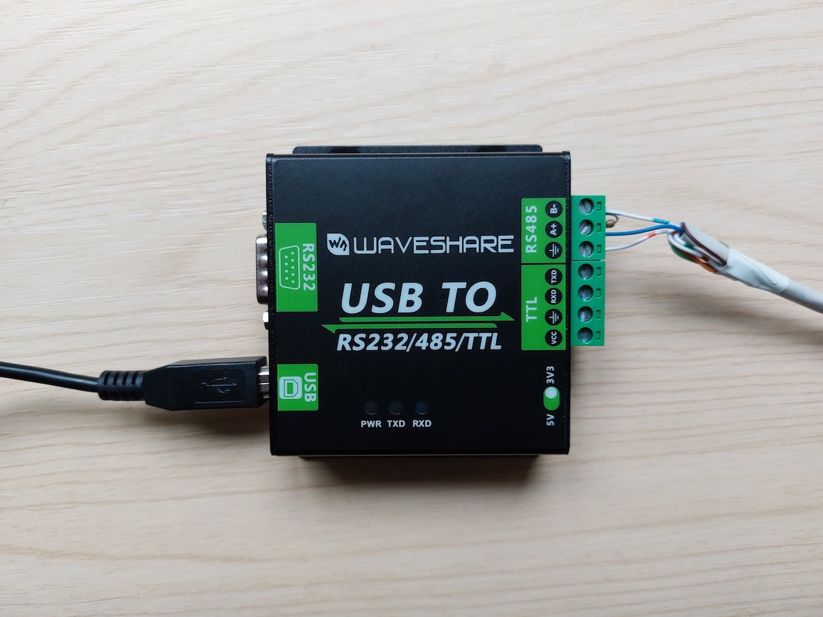
I bought a Waveshare isolated USB to RS485 adapter. This is based on the FT232RL chipset which automatically handles the turning on and off of the transmit driver, so there's nothing in the code here to do this. There are cheaper RS485 adapters available, but the isolation makes me feel more comfortable about electrical safety.
The device appears by default as /dev/ttyUSB0 if you have no other
serial-USB adapters, although I recommend you refer to it using one of the
links under /dev/serial/by-id/ or /dev/serial/by-path/ because this
avoids problems when you have multiple USB devices, which may choose an
arbitrary ordering at bootup.
Data logger connection
Warning
Modifying the data logger is not for the faint hearted!
You will almost certainly void the warranty on your logger, and possibly the complete system. Do not proceed unless you are 100% confident that you can do this safely.
Consider the alternative approaches first.
Disconnect the logger from the inverter.

Prising open the logger is easy: push two small screwdrivers into two adjacent opening points.
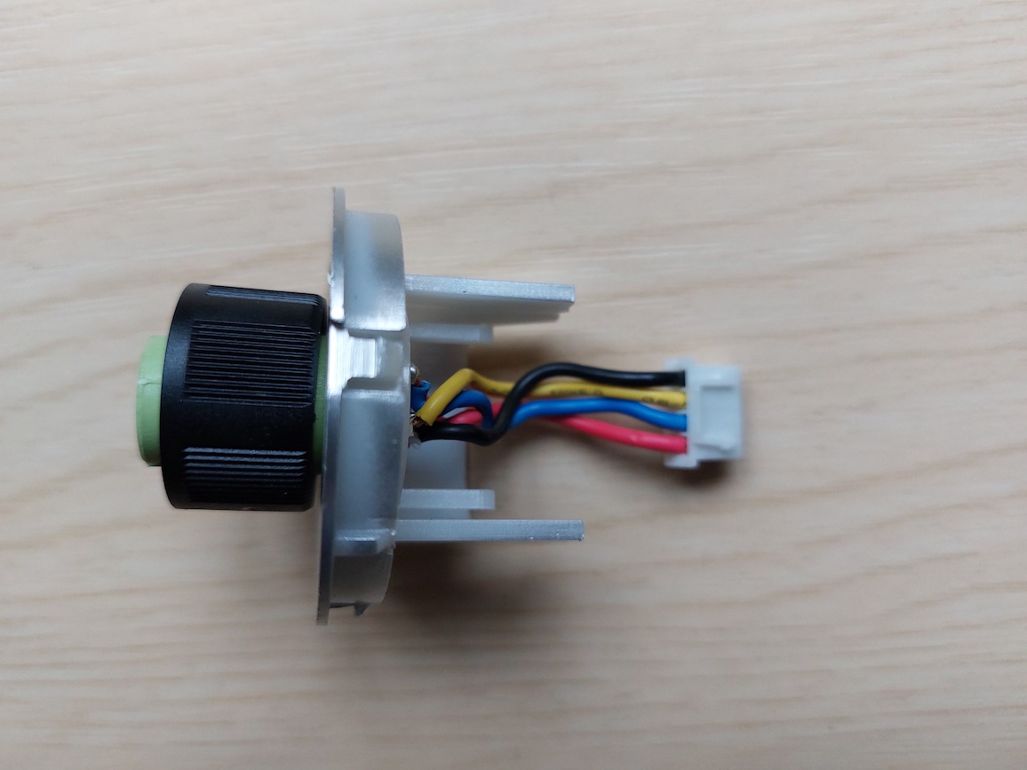
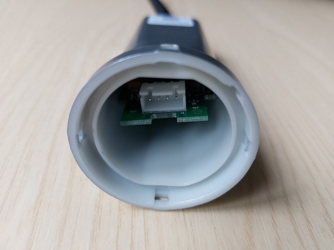
The circuit board can be removed by unscrewing the wifi antenna, removing the nut and washer on the antenna connector, and then pulling the board out.
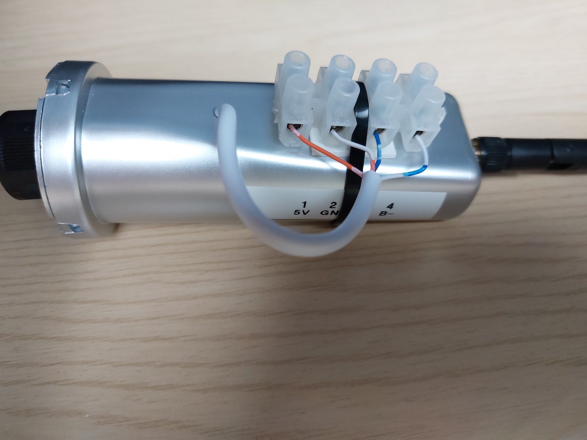
I soldered on four extra connections in parallel with the existing connector:
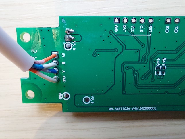
Then I drilled a hole in the side of the logger case and brought the connections out to a terminal block for flexibility, using the numbering from the Exceed connector pins:
- 5V (red)
- Ground (black)
- A+ (yellow)
- B- (blue)
In future I might use something like as Raspberry Pi Zero W, and it could be powered from the 5V line. Otherwise, make sure you don't connect anything to 5V.
The wifi data logger doesn't appear to have a 120 ohm terminating resistor, so I added one at the USB-RS485 end.